Functional Safety according to IEC 61508 / ISO 26262 / IEC 62304
APIS IQ-RM PRO is now Functional Safety Approved (TÜV Certified).
See more about APIS IQ-RM PRO, click here
The features available in the APIS IQ-Software are based on the underlying documents IEC 61508 and ISO 26262. Specific requests made by APIS IQ-Software version 5.1 (2006) users resulted in taking IEC 61508 into consideration. As of 2009, ISO 26262 was supported as well. * Available for Pro Versions of IQ-Software
Practice-oriented features were developed in collaboration with various interest groups. The following overview offers some varied application scenarios.
The quantitative analysis for the functional safety of a system is becoming more and more important. Based on failure net methods, APIS IQ-Software offers to evaluate and calculate the necessary criteria.
For the top level failures of a system, IQ-Software calculates the norm specific values, for example PFH value (Probability of dangerous Failure per Hour: Average probability of failure of a safety function working in high demand or continuous mode of operation) or SFF value (Safe Failure Fraction: Percentage part of safe failures and dangerous detected failures of a safety function or a subsystem related to all failures) for IEC 61508. The computed values are compared to the specifications and divergences that are reported functional safety.
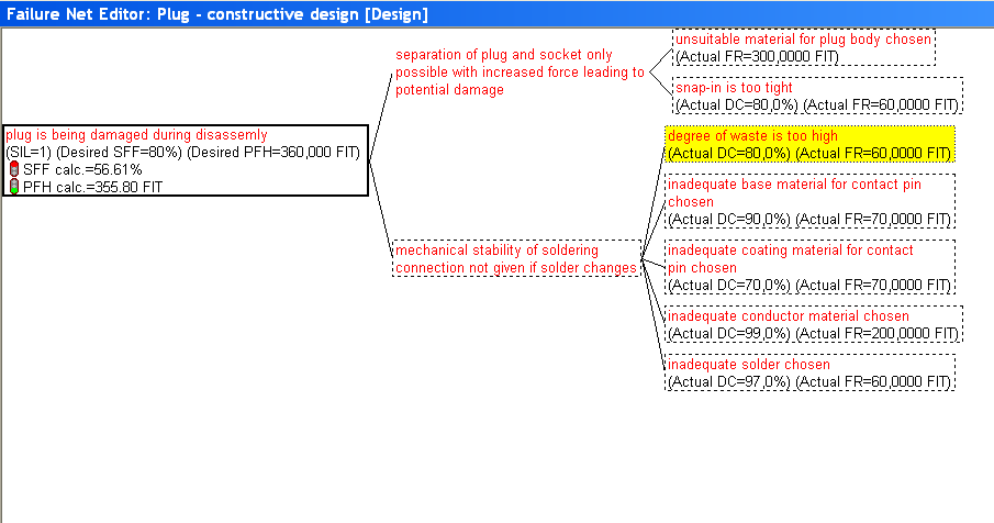
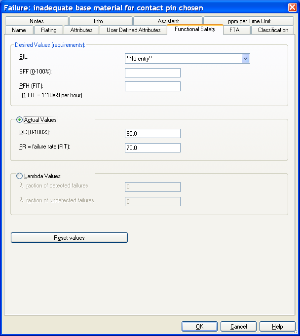
The classification of top failures according to risk categories ((Automotive) Safety Integrity Level ((A)SIL). The higher the (A)SIL of a safety-related system, the lower the probability that it will not perform the required safety functions) as well as their diagnostic coverage (DC) and the failure rate (FIT value) of the basic failures can be input in the Properties Dialogue or the Object Inspector.
- Option 1: Fault Trees (FTA) with minimal cut sets and export into XLS or XLSX
- Option 2: Calculation options based on failure net (Failure Net Calculation)
- Option 3: Calculation options based on failure net (Failure Net Calculation) with additional objects from mechatronics FMEA, i.e. operating condition, error detection, and error response.
- Option 4: Calculation options based on failure net (Failure Net Calculation) with additional objects from mechatronics FMEA (see option 3) and taking time analyses (timing) into account, in particular the Fault Tolerance Time (FTT). The Graph Editor in particular is helpful to handle complex cases.
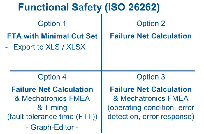
Figure: Overview of application scenarios
Option 1: FTA with minimal cut set
If the single point faults and double point faults are determined in a qualitative analysis, you can establish the minimal cut set of a fault tree for this purpose. The validation analysis is usually done with other contents in an external document for single point faults and double point faults. The required data are transferred into a suitable format (MS Excel) by exporting the minimal cut set.
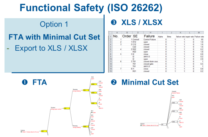
Figure: Creation of an XLS/XLSX file based on minimal cut sets
1. Create FTA
2. Verify minimal cut set
3. Export into XLS / XLSX
Option 2: Working with the failure net
Calculation of actual values and comparison with target values (claim level).
The field of quantitative analyses is about calculating for each safety goal, whether the target values are met, i.e. whether the claim level is reached.
In this regard, you can resort to the familiar and established failure net of the APIS IQ-Software. The target value is recorded with the top failure, the violation of the security goal. The actual values are recorded with all connected basic failures (= causes) and, in addition, it is documented at a suitable position in the failure net, whether diagnostic coverage (DC value) is available.
With regard to ISO 26262, it is additionally required to analyze latent failures and to record the safe portion in accordance with the specifications for calculation. In this section, the APIS IQ-Software supports and facilitates the work by taking the function relationships (function net) into account.
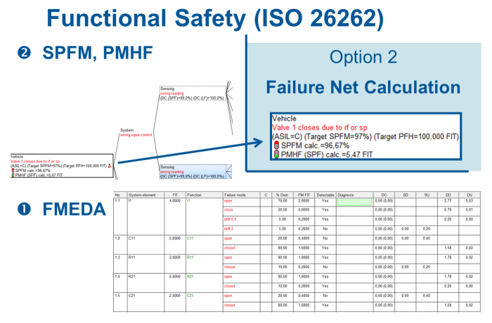
Figure: Analysis of single point faults based on the failure net
It is most convenient to record the actual values of basic failures by means of the FMEDA form. Either you can record the values directly with the failure types or you can use a distribution model.
You can save calculation formulas to determine a component FIT, e.g. SN 29500, with the CARM NG Server. It is then sufficient to select the type of component and to enter the required working/application conditions, e.g. the temperature.
The fault table shows all the information necessary for each safety goal in the resulting document.
1.System modeling with function and failure nets
2.Determination of safety goal with claim level for SPFM, LFM, and PMHF
3.Recording of FIT values, e.g. in FMEDA form
4.Recording of DC values with failures
5.Check calculation basis (FIT and DC) for completeness
6.Issue fault table for each safety goal
Option 3: Extending the failure net with components from mechatronics FMEA
For some of the systems, it is reasonable to integrate the operating condition, error detection, and error response into the failure net. This is possible with the mechatronics FMEA feature enabled.
You can assign a diagnostic coverage value to the failure detection.
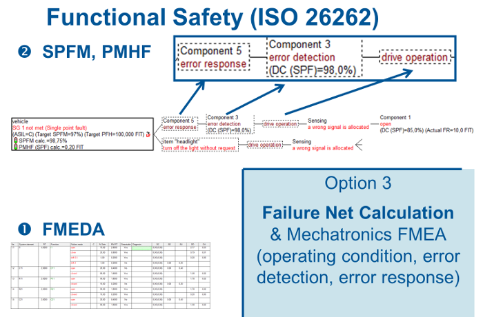
Figure: Objects from mechatronics FMEA in failure net and DC in error detection
1.Structure modeling with function and failure nets
2.Supplement the failure nets with error detection and error response
3.Determine the safety goal and claim level for SPFM, LFM, and PMHF
4.Recording of FIT values, e.g. in FMEDA form
5.Recording of DC values with failures or better with error detection
6.Check calculation basis (FIT and DC) for completeness
7.Issue fault table for each safety goal
Option 4: Supplement the failure relationships for FTT analysis
For analyses regarding the Functional Safety, you need to check whether the implemented error detections and error responses run within the given fault tolerance time (FTT).
The target value of the fault tolerance time is defined with the top failure of the safety goal. Then, the related failure detection time (FDT) is recorded for the error detections and the related failure reaction time (FRT) for the error responses. The IQ-Software then checks for each safety goal, whether the sum of failure detection time and failure reaction time is within the target value (FTT) or not.
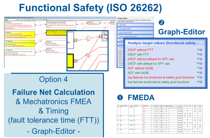
Figure: Objects from mechatronics FMEA in failure net and DC in error detection
The analysis of this time behavior is possible in the Graph Editor, which, on the one hand, contains the appropriate display options and in which, on the other hand, the suggestion list is provided with supporting control options.
1.Structure modeling with function and failure nets
2.Supplement the failure nets with error detection and error response
3.Determine the safety goal and claim level for SPFM, LFM, and PMHF
4.Determine the fault tolerance time (FTT) for each violation of the safety goal
5.Determine the fault detection time (FDT) for the error detection and the fault reaction time (FRT) for the error response
6.Recording of FIT values, e.g. in FMEDA form
7.Recording of DC values with failures or better with error detection
8.Check in Graph Editor, whether the claim level is complied with regarding the time behavior
9.Check calculation basis (FIT and DC) for completeness
10.Issue fault table for each safety goal
Outlook, training courses, and services
The subject of Functional Safety is in the flow. We make sure to meet the practical demands by means of constant contact to users and monitoring the standardization activities.
Important issues for the future are the connection to external systems, i.e. data exchange, and the update of the parameters to be taken into account.
The APIS IQ Software has numerous features and supports established concepts. They help the experienced user in the field of Functional Safety. The CARM Server with CSS Module and the CARM NG Server with CSS Functional Safety respectively simplify the editing of complex models and speed it up.
We may kindly refer to the following further information:
Information and sample data are available for download at Downloads (in Reference Documents / Functional Safety).
Information on the features of the latest version 6.5 are available at Downloads
If you have any questions, please write an e-mail to info@apis.de