You are in the MSR form and have received the following information (e.g. by moving the mouse pointer over ![]() ):
):
No safety mechanism has yet been derived from the “action in customer operation” anchored here.
By right-clicking the info icon, you will see the “Open web page (note)” which leads you to further information on this topic.
The above note indicates to the IQ-user that a safety mechanism still needs to be derived from the “action in customer operation”, in order to create a link in the Failure Graph (Failure Net). In order to derive safety mechanisms from actions, it is advised to use the context menu in the MSR form (right mouse button) and execute the command “Derive Safety Mechanisms from Actions”. The following images illustrate this process. Note that your display-option settings may vary and thus not show all elements you can see here.
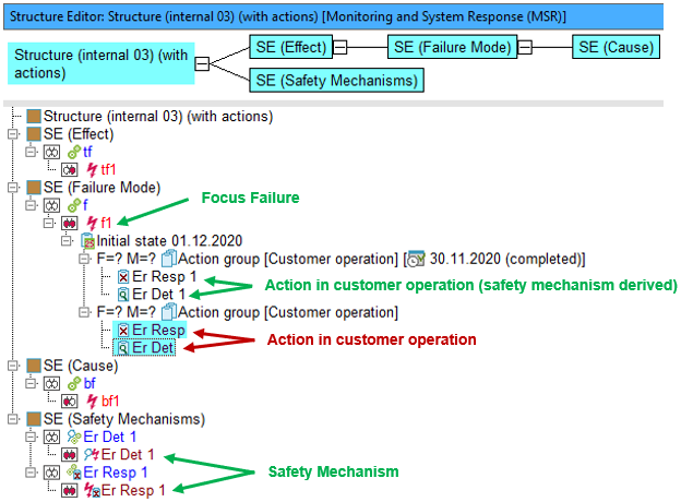
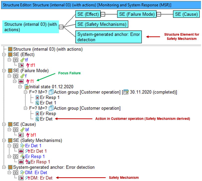
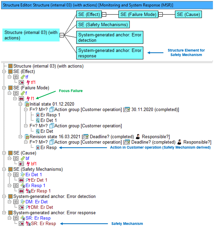
The initial situation in the Structure Editor shown below shows that for failure f1 (focus failure) there is an initial state with two action groups of the type “Customer Operation”, which themselves each contain two actions. Safety mechanisms have already been derived from two out of four of these actions, but not yet from the other two. For the sake of clarity, the derived safety mechanisms have been placed in a separate structure element.
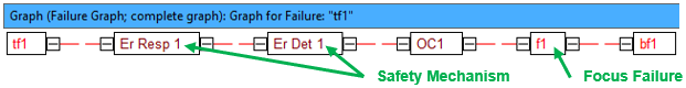
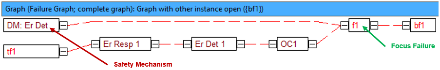
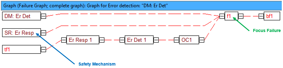
The Failure Graph gives a better understanding of how the failures and safety mechanisms are linked to each other.
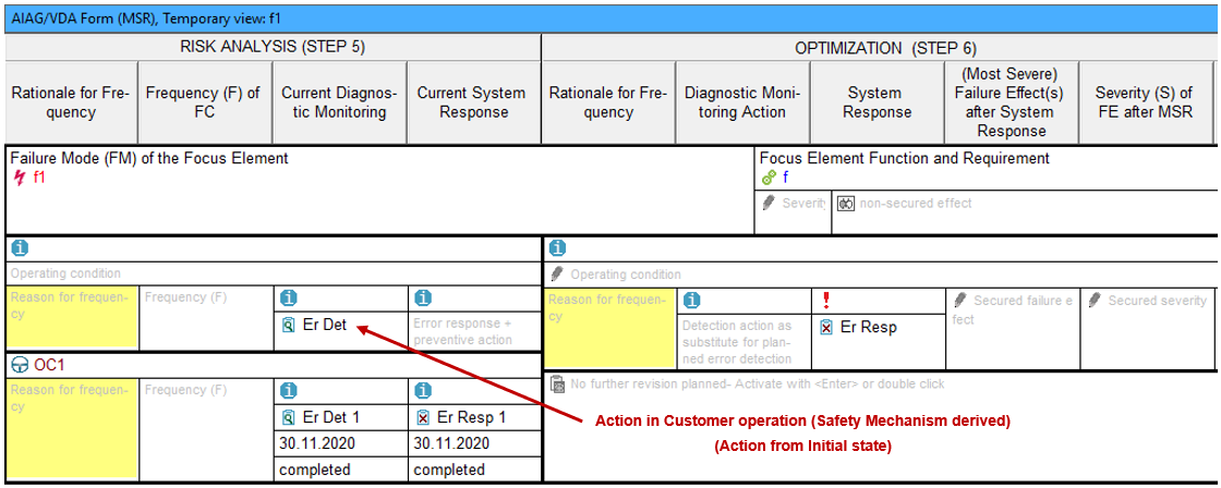
This is how these elements look in the MSR Form.
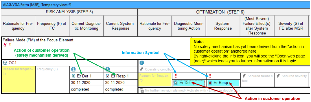
The rule here is that actions in customer operation that have an initial state and from which no safety mechanism has yet been derived are first placed in the “OPTIMIZATION (STEP 6)”, as is done here with Er Det and Er Resp.
The information icon that appears at both Er Det and Er Resp indicates to you that a safety mechanism also needs to be derived here, as described above. If, for example, a safety mechanism is derived for Er Det, this creates a new IQ-object which must be anchored in the structure. This “anchoring” occurs via a new system element generated by the IQ-Software. In the case above, the structure element has a safety mechanism of type “Error detection”. As such, the IQ-Software generates the element with the following name “System-generated anchor: Error detection”.
In our example, both Er Det 1 and Er Resp 1, also located in “initial state”, have already had safety mechanisms assigned via this process. As such, both appear in “RISK ANALYSIS (STEP 5)”, as this is where initial state elements would appear in the MSR Form.
The following images show in various editors (Structure Editor, Failure Graph, MSR Form) an example, whereby, out of the action Er Det a corresponding safety mechanism with the same name (including prefix “DM:”) is created.
Because the action Er Det is anchored at failure f1, the IQ-Software knows that the safety mechanism derived from it – here assigned with the name “DM: Er Det” – must show up in the Failure Graph as an effect of f1. Therefore, the Failure Graph shown below results automatically.
Das MSR-Formblatt schließlich hat das nachfolgende Aussehen:
As expected, the action Er Det can now be found in the MSR form “RISK ANALYSIS (STEP 5)”. This is because, on the one hand, it is located in an initial state and, on the other hand, because a safety mechanism (DM: Er Det) has been derived from it.
Further observation:
Finally, we will use the example of the Er Resp action to show what happens when a safety mechanism is generated from an action, this time in a “revision state”. The Structure Editor looks as follows:
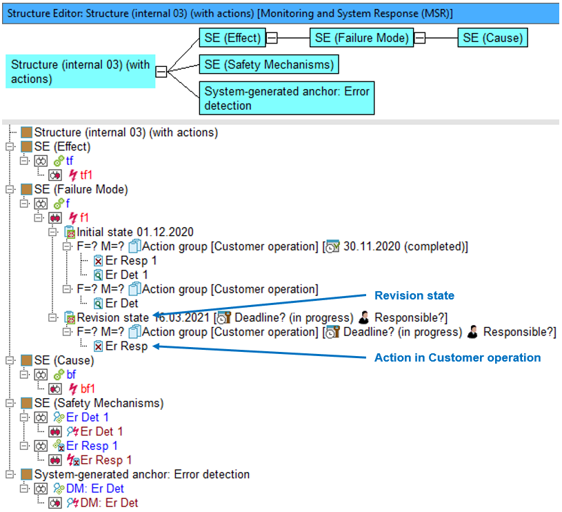
Moving the action Er Resp to a revision state does not change how the MSR Form looks. However, if a safety mechanism is generated from Er Resp in a revision state via the MSR form, this has consequences in the Structure Editor, in the Failure Graph and in the MSR form. The IQ-Software automatically creates the “system-generated” element (Error response), as can be seen below:
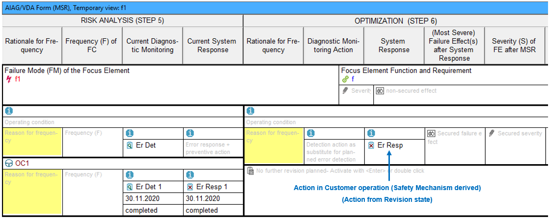
The Failure Graph, in this case, looks as follows. As an FMEA creator, you can now manually adjust how failures, error responses and detections link to each other according to your Risk Analysis.
The following image shows the MSR Form, whereby the revision state deadline has been set to “completed”. Because the safety mechanism Er Resp was derived from an action in a “revision state”, the data is found in “OPTIMIZATION (STEP 6)”.